The basic function of a filtering circuit is to allow or prevent current of a certain frequency from passing through, minimizing the AC component in the pulsating DC voltage, retaining its DC component, reducing the ripple factor of the output voltage, and making the waveform smoother. In filtering circuits, devices with special impedance characteristics for alternating current are mainly used, such as capacitors and inductors. The following is an in-depth analysis of the filtering circuit, with super detailed graphic and textual explanations, hoping to be helpful to everyone!
Types of filtering circuits:
There are mainly the following types of filtering circuits: capacitive filtering circuit, which is the most basic filtering circuit; π - type RC filtering circuit; π - type LC filtering circuit; Electronic filter circuit.
1. Characteristics of unidirectional pulsating DC voltage
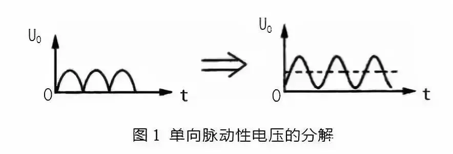
As shown in Figure 1 (a). It is a unidirectional pulsating DC voltage waveform. From the figure, it can be seen that the directionality of the voltage is consistent at all times, but the amplitude of the voltage fluctuates. That is, on the time axis, the voltage shows periodic changes, so it is pulsating.
But according to the principle of waveform decomposition, this voltage can be decomposed into a DC voltage and a set of AC voltages with different frequencies, as shown in Figure 1 (b). In Figure 1 (b), the dashed line represents the unidirectional pulsating DC voltage U. The DC component in UO is represented by the solid line, while the AC component in UO is represented by the solid line.
2. Principle of capacitor filtering
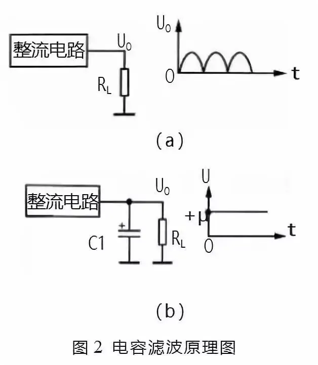
According to the above analysis, due to the unidirectional pulsating DC voltage, it can be decomposed into two parts: AC and DC. In the filtering circuit of the power supply circuit, the AC component in the voltage can be filtered out by utilizing the "isolated DC to AC" characteristic and energy storage characteristic of capacitors, or by utilizing the "isolated DC to AC" characteristic of inductors. Figure 2 shows the principle diagram of capacitive filtering.
Figure 2 (a) shows the output circuit of the rectifier circuit. The output of the AC voltage after rectification circuit is unidirectional pulsating DC, which is the UO in the circuit.
Figure 2 (b) shows the capacitor filter circuit. Due to the fact that capacitor C1 is equivalent to an open circuit to DC current, the DC voltage output by the rectifier circuit cannot pass through C1 to ground, and can only be applied to the load RL as shown in the RL diagram. For the AC component output by the rectifier circuit, due to the large capacity and small capacitance of C1, the AC component flows to the ground through C1 and cannot be added to the load RL. In this way, through the filtering of capacitor C1, the required DC voltage+U is extracted from the unidirectional pulsating DC current.
The larger the capacity of the filtering capacitor C1, the smaller its capacitance to AC components, resulting in a smaller residual AC component on the load RL and better filtering effect.
3. Principle of Inductive Filtering
Figure 3 shows the principle diagram of inductive filtering. Due to the fact that inductor L1 acts as a path for direct current, the DC voltage output by the rectifier circuit is directly applied to load RL.
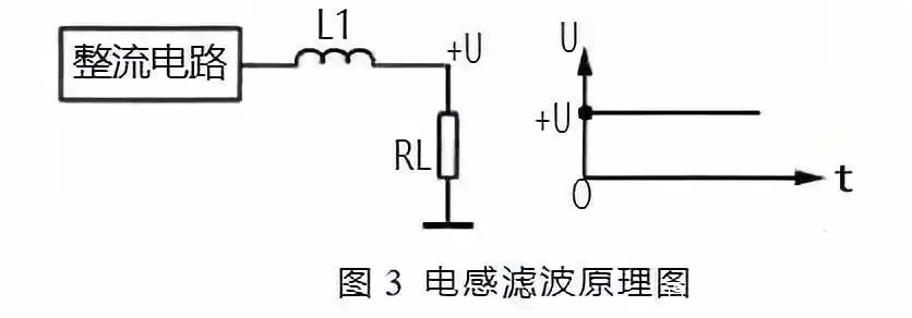
For the AC component output by the rectifier circuit, due to the large inductance and reactance of L1, it has a significant hindering effect on the AC component, preventing AC power from flowing through C1 to the load RL. In this way, through the filtering of inductor L1, the required DC voltage+U is extracted from the unidirectional pulsating DC current.
The larger the inductance of the filtering inductor L1, the greater the inductance of the AC component, resulting in a smaller residual AC component on the load RL and better filtering effect. However, the DC resistance will also increase.
Diagram recognition method for π - type RC filter circuit
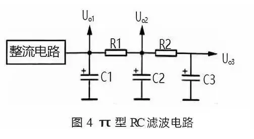
The π - type RC filter circuit is shown in Figure 4. C1, C2, and C3 in the circuit are three filtering capacitors, R1 and R2 are filtering resistors, and C1, R1, and C2 form the first π - type RC filtering circuit, C2, R2, and C3 form the second section of the π - type RC filtering circuit. Due to the form of this filtering circuit resembling the Greek letter π and the use of resistors and capacitors, it is called a π - type RC filtering circuit.
The principle of the π - type RC filter circuit is as follows:
(1) The filtering principle of this circuit is that the voltage output from the rectifier circuit is first filtered by C1 to remove most of the AC components, and then added to the filtering circuit composed of R1 and C2. The capacitance impedance of C2 and R1 form a voltage divider circuit. Due to the small capacitance impedance of C2, the attenuation of the AC component's voltage divider is significant, achieving the purpose of filtering. For direct current, due to the DC blocking effect of C2, the R1 and C2 voltage divider circuits do not have a voltage attenuation effect on the DC, so the DC voltage is output through R1.
(2) When the size of R1 remains constant, increasing the capacity of C2 can improve the filtering effect. When the capacity of C2 remains constant, increasing the resistance of R1 can improve the filtering effect. However, the resistance value of the filtering resistor R1 cannot be too large, because the DC current flowing through the load needs to flow through R1, which will generate a DC voltage drop on R1 and reduce the DC output voltage Uo2. The larger the resistance of R1 or the greater the current flowing through the load, the greater the voltage drop across R1, resulting in a lower DC output voltage.
(3) C1 is the first filtering capacitor, increasing the capacity can improve the filtering effect. However, when C1 is too large, the charging time for C1 during startup is very long, and this charging current flows through the rectifier diode. When the charging current is too large and the time is too long, it will damage the rectifier diode. So using this π - type RC filtering circuit can reduce the capacity of C1, and further improve the filtering effect by designing the values of R1 and C2 reasonably.
(4) There are three DC voltage output terminals in this filtering circuit, which output Uo1 Uo2 and Uo3 are three sets of DC voltages. Among them, Uo1 is only filtered by capacitor C1; Uo2 went through C1 The filtering effect is better due to the filtering of R1 and C2 circuits, The communication component in Uo2 is smaller; Uo3 has undergone filtering through two filtering circuits, and the filtering effect is the best, so the AC component in Uo3 is the least.
(5) The magnitude of the three DC output voltages is different. Uo1 has the highest voltage, which is usually applied directly to the power amplifier circuit or to the circuit that requires the highest DC operating voltage and current; The voltage of Uo2 is slightly lower due to the voltage drop caused by resistor R1 on the DC voltage; The Uo3 voltage is the lowest, and this voltage is generally supplied to the front-end circuit as the DC working voltage, because the DC working voltage of the front-end circuit is relatively low and requires less AC component in the DC working voltage.
Diagram recognition method for π - type LC filter circuit
The π - type LC filter circuit is shown in Figure 5. The π - type LC filter circuit is basically the same as the π - type RC filter circuit. This circuit only replaces the filtering resistor with a filtering inductor, because the filtering resistor has the same resistance to DC and AC electricity, and the filtering inductor has a larger resistance to AC inductance and a smaller resistance to DC electricity. This can improve the filtering effect without reducing the DC output voltage.
In the circuit of Figure 5, the unidirectional pulsating DC voltage output by the rectifier circuit is first filtered by capacitor C1 to remove most of the AC components, and then added to the L1 and C2 filtering circuits.
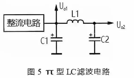
For communication components, L1 has a high inductance to it, resulting in a large AC voltage drop on L1 and a small AC component applied to the load.
For DC power, since L1 does not exhibit inductive reactance, it is equivalent to a path. At the same time, the filtering inductor uses a thicker wire diameter and a small DC resistance, which basically does not cause voltage drop to the DC voltage. Therefore, the DC output voltage is relatively high, which is the main advantage of using an inductive filter.
Electronic filter image recognition method
1. Electronic filter
Figure 6 shows an electronic filter. VT1 in the circuit is a transistor that functions as a filter, C1 is the base filtering capacitor of VT1, R1 is the base bias resistor of VT1, RL is the load of this filtering circuit, and C2 is the filtering capacitor for the output voltage.
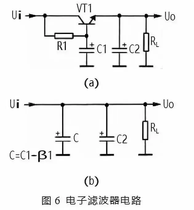
The working principle of electronic filtering circuit is as follows:
① VT1 in the circuit R1 and C1 form an electronic filter circuit, which is equivalent to a capacitor with a capacity of C1 × β 1. β 1 is the current amplification factor of VT1, while the current amplification factor of the transistor is relatively large, so the equivalent capacitance is large, indicating that the filtering performance of the electronic filter is very good. The equivalent circuit is shown in Figure 6 (b). C in the figure is the equivalent capacitance.
② R1 and C1 in the circuit form an RC filtering circuit, On the one hand, R1 provides base bias current for VT1, and on the other hand, it is also a filtering resistor. Since the current flowing through R1 is the base bias current of VT1, which is very small, The resistance value of R1 can be relatively large, which improves the filtering effect of R1 and C1, and reduces the AC component in the DC voltage at the base of VT1. Due to the characteristic of the emitter voltage following the base voltage, the AC component in the VT1 emitter output voltage is also minimal, achieving the purpose of filtering.
③ In electronic filters, filtering is mainly achieved through R1 and C1, which are also RC filtering circuits, but different from the RC filtering circuit introduced earlier. The DC current flowing through the load in this circuit is the emitter current of VT1, and the current flowing through the filtering resistor R1 is the base current of VT1. The base current is very small, so the resistance of the filtering resistor R1 can be set high (for good filtering effect), but it will not cause a significant decrease in the DC output voltage.
④ The resistance value of R1 in the circuit determines the base current of VT1, which in turn determines the voltage drop between the collector and emitter of VT1, and thus determines the output DC voltage of VT1 emitter. Therefore, changing the size of R1 can adjust the DC output voltage+V.
Electronic voltage regulator filter
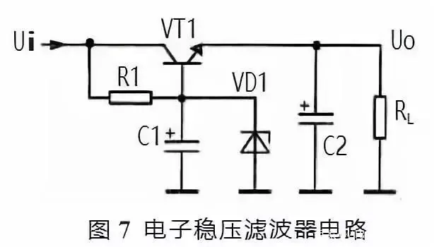
Figure 7 shows another type of electronic voltage regulator filter, in which a voltage regulator diode VD1 is connected between the base and ground of VT1 compared to the previous circuit. The principle of electronic voltage regulation is as follows:
After connecting the voltage regulator diode VD1 between the base and ground of VT1, the input voltage is passed through R1 to put the voltage regulator diode VD1 in a reverse bias state. At this time, the voltage regulation characteristics of VD1 stabilize the base voltage of the VT1 transistor, so that the DC voltage output from the VT1 emitter is also relatively stable. Note: The stability characteristics of this voltage are determined by the voltage stabilization characteristics of VD1 and are not related to the electronic filter circuit itself.
R1 is also the current limiting protection resistor for VD1. After adding the voltage regulator diode VD1, changing the size of R1 cannot change the output voltage of the emitter of VT1. Due to the PN junction voltage drop at the emitter of VT1, the output voltage of the emitter is slightly smaller than the voltage regulator value of VD1.
C1, R1, and VT1 also form an electronic filter circuit, which plays a filtering role.
In some cases, in order to further improve the filtering effect, a dual tube electronic filter circuit can be used, where two electronic filter tubes form a composite tube circuit. The total current amplification factor is the product of the current amplification factors of each tube, which can obviously improve the filtering effect.
Summary:
Regarding the analysis of power filter circuits, the following points should be noted:
(1) When analyzing the working principle of filter capacitors, the main use is the "isolated through AC" characteristic of capacitors, or the charging and discharging characteristics. That is, when the rectifier circuit outputs a unidirectional pulsating DC voltage, the filter capacitor is charged. When there is no unidirectional pulsating DC voltage output, the filter capacitor discharges the load.
(2) When analyzing the working principle of filter inductors, the main understanding is that inductors have a small resistance to direct current and no inductive reactance, while they have inductive reactance to alternating current.
(3) When analyzing electronic filter circuits, it is important to understand that the capacitor on the base of the electronic filter tube is a critical component for filtering. In addition, to analyze the DC circuit, electronic filter tubes have base current, collector current, and emitter current. The current flowing through the load is the emitter current of the electronic filter tube. Changing the magnitude of the base current can adjust the voltage drop between the collector and emitter of the electronic filter tube, thereby changing the magnitude of the DC voltage output by the electronic filter tube.
(4) The electronic filter itself does not have a voltage stabilization function, but adding a voltage regulator diode can make the output DC voltage relatively stable.

